The Four Placement Decisions in Every System
People asking where a radon mitigation system goes are usually asking one of four separate questions: where the pipe enters the ground, where the pipe travels, where the fan sits and where the air comes out. Answering them as a single question is what produces poorly placed systems.
The suction point is chosen by soil gas physics. The riser route is chosen by building layout and aesthetics. The fan location is governed by safety rules about where pressurized radon-laden pipe may run. The exhaust point is governed by dispersion and re-entrainment. These constraints sometimes conflict, and resolving them is the actual design work.
- Suction point: where the pipe penetrates the slab or membrane
- Riser: the vertical and horizontal pipe route through or outside the building
- Fan: mounted in an attic, garage attic or on the exterior wall, never in conditioned living space below occupied area
- Exhaust: terminated above the eave, away from openings
Selecting the Suction Point
The suction point is placed where it can establish the widest possible pressure field under the foundation. In practice, that means near the center of the slab area being treated when access allows, over the most permeable sub-slab material available, and away from footings that would block lateral airflow.
Sub-slab communication testing is how this is verified rather than guessed. A test hole is drilled at candidate locations and vacuum is measured at distant points across the slab; if the pressure field extends across the whole area, one point suffices. If a footing, an added-on section or a poorly drained soil pocket interrupts it, additional suction points are needed.
Where a home has a sump pit connected to perimeter drain tile, the pit is frequently the best suction location available, because the drain tile loop distributes suction around the entire foundation perimeter. Sealing the pit with a gasketed lid and drawing from it converts the largest entry point in many Indianapolis basements into the system's greatest asset.
Why Perimeter Placement Is a Compromise
Suction points are often forced toward the perimeter or into a utility room because the center of the slab is under finished flooring the homeowner does not want cored. That is a legitimate tradeoff, but it usually means a higher static pressure fan and sometimes a second point, since the pressure field has to travel farther against the footing rather than radiating outward from the middle.
Basement and Slab Foundations
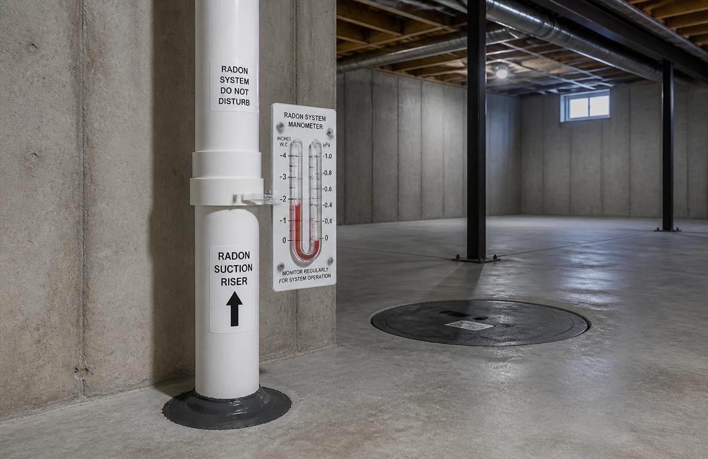
In basements and slab-on-grade homes, the suction point is a cored hole roughly four to six inches across with a small void excavated beneath it, sealed to the slab with a pipe boot and polyurethane sealant. Location is chosen for pressure field coverage first, then for how cleanly the riser can leave the room.
Utility rooms, unfinished storage areas and closets are common choices because they combine slab access with a clear vertical path to the attic or exterior wall. Finished basements complicate this, which is why the riser route is often decided at the same moment as the suction point rather than afterward.
Hollow block foundation walls introduce a second pathway independent of the slab. Where block cores communicate with soil gas, either the top course is sealed or the wall cavity is tied into the system with a dedicated connection, otherwise the slab suction point pulls from the block cavity instead of the soil and the pressure field collapses.
Crawl Spaces and Combination Foundations
Crawl spaces have no slab to core, so the suction point sits beneath a sealed membrane instead. A reinforced vapor barrier is laid across the exposed soil, sealed at piers, plumbing penetrations and the foundation perimeter, and the suction pipe is set underneath it. Placement is generally near the center of the covered area, away from the access hatch and away from perimeter vents.
Combination foundations, a basement on one side and a crawl space under an addition, are extremely common in Central Indiana housing stock. These often require two suction points: one sub-slab and one sub-membrane, joined into a single riser and fan when static pressure allows, or run as two systems when the pressures are too dissimilar to balance on one fan.
Crawl space membrane systems also change where the pipe can run, because the horizontal pipe under the house must maintain slope back toward the suction point so condensate drains rather than pooling in a low spot.
Interior Versus Exterior Riser Routing
Interior routing takes the pipe up through closets, mechanical chases or the garage into the attic, where the fan is mounted and the exhaust exits through the roof. It keeps PVC off the facade, keeps the pipe warm enough to limit condensate freezing and produces the least visible result, but it requires an available vertical path and framing penetrations.
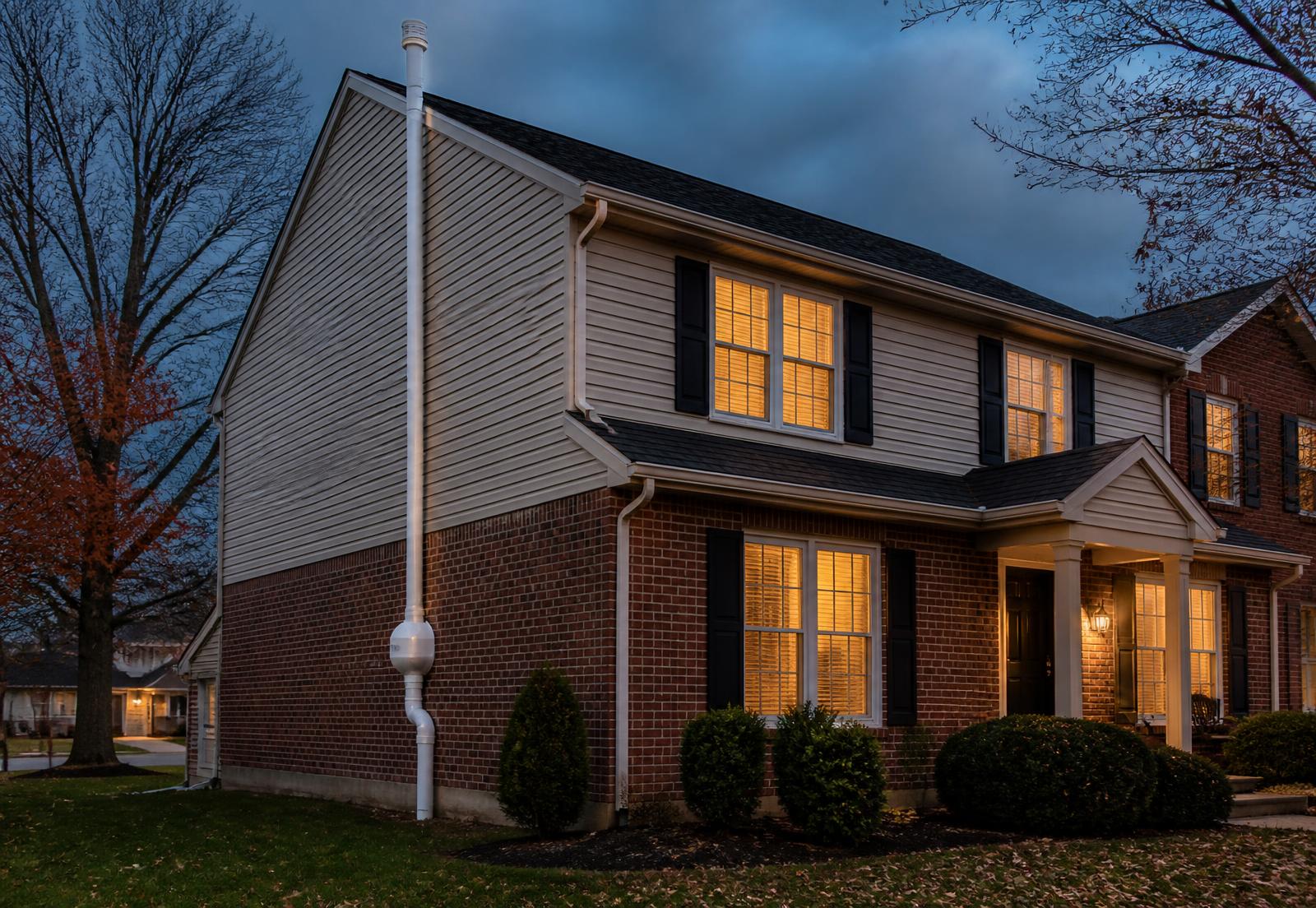
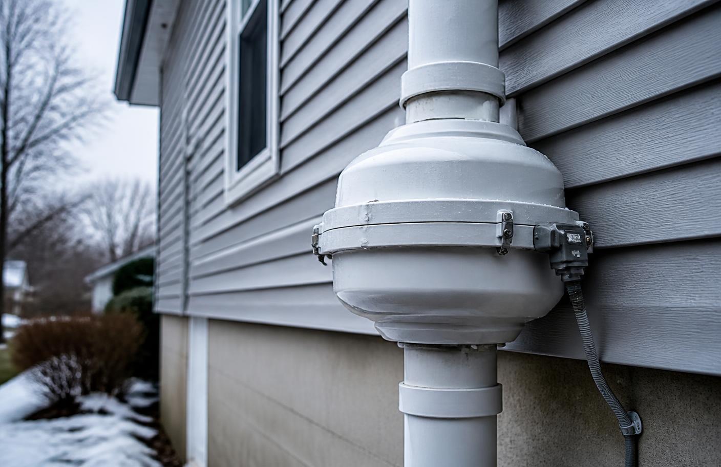
Exterior routing takes the pipe out through the rim joist or foundation wall low on the building and runs it up the outside to a fan mounted on the wall, with exhaust terminating above the eave. It is faster, avoids cutting through finished interior space and simplifies later fan service, but it puts a visible stack on the house and exposes the pipe to weather.
Neither route is inherently better. What matters is that the choice is discussed rather than defaulted to, and that exterior pipe is supported, sealed at the penetration and, where appearance matters, painted to match the siding.
- Interior riser: least visible, requires a usable chase, fan located in attic
- Exterior riser: fastest, easiest to service, visible stack on the facade
- Either route must avoid long unsupported horizontal runs that trap condensate
- Penetrations through the envelope must be sealed and flashed properly
Where the Fan Can and Cannot Go
The pipe downstream of the fan is under positive pressure and carries radon-laden air, so a leak on that side pushes radon into whatever space surrounds it. That single fact drives the placement rule: fans are installed in unconditioned attics, garage attics or outdoors on an exterior wall, never in a basement, crawl space or any conditioned interior space beneath the occupied area of the home.
Beyond compliance, fan placement affects noise and service access. A fan mounted directly above a bedroom ceiling transmits low-frequency hum through framing; shifting it a few feet toward a hallway or the garage side of the attic usually resolves it. Exterior fans should be mounted where the homeowner can see the manometer without a ladder, and where a future replacement does not require dismantling the whole riser.
Fans are also mounted vertically in most installations so condensate drains back down the pipe toward the suction point rather than collecting in the housing, which shortens fan life.
Exhaust Termination Requirements
The exhaust point is where the whole system either disperses radon safely or quietly recirculates it. Standard practice terminates the exhaust above the roof eave line, at least ten feet above grade, and well away from operable windows, doors, and other openings into the home or adjacent buildings, so the discharged air dilutes into outdoor atmosphere before it can be drawn back in.
Terminations that discharge into soffit vents, under a deck, beside a second-story window or into an attached garage are among the most consequential installation defects, because the system continues to run and the gauge continues to read normally while a portion of the exhaust re-enters the building.
Prevailing wind, neighboring structures on tight lots and roof geometry all influence the final termination location, which is why it is decided on site rather than on a drawing.
- Discharge above the eave line, vertically upward
- Clear of operable windows, doors and air intakes by the required separation
- Never into soffits, attics, garages, crawl spaces or under decks
- Positioned considering neighboring structures on narrow lots
Attached Garages, Tight Lots and Difficult Sites
Attached garages are useful and hazardous in equal measure. A garage often offers the cleanest riser path from the basement to the attic without touching finished space, but the garage itself must never receive the exhaust, and pipe joints inside the garage must be sound because any leak downstream of the fan discharges into a space that shares air with the house.
Tight urban lots, common in older Indianapolis neighborhoods, restrict exterior routing because the required separation from a neighbor's windows may be impossible on the side elevation. In those cases the system usually moves to an interior riser with a roof termination, even though it is more labor.
Other site conditions that redirect placement include finished basements with no chase, historic facades where an exterior stack is unacceptable, shallow crawl spaces with insufficient working clearance, and homes where the electrical panel location makes a dedicated fan circuit easier to reach from one side of the building than the other.
Common Placement Mistakes
Most underperforming systems are not underpowered, they are misplaced. The pattern is consistent: the suction point went where it was convenient to core rather than where the pressure field would spread, or the exhaust went where the pipe already was rather than where the air needed to disperse.
These errors are correctable, usually by adding a suction point, resealing an entry path or extending and relocating the termination, but they are far cheaper to avoid at design time than to fix after a failed retest.
- Single suction point on a segmented or added-onto slab without communication testing
- Suction point placed adjacent to a footing that blocks the pressure field
- Sump pit left unsealed while suction is drawn elsewhere
- Fan installed in the basement or in conditioned space below living area
- Exhaust terminated below the eave or near a window or soffit vent
- Crawl space membrane unsealed at piers, walls or the access hatch
- Horizontal pipe run with a sag that fills with condensate and chokes airflow
Why Placement Has to Be Site-Specific
Two identical floor plans on the same street can require different systems, because sub-slab aggregate, backfill compaction, drain tile presence, additions and finished space differ house to house. This is the reason a phone quote cannot specify placement, and the reason the same contractor may propose one suction point on one home and three next door.
The practical consequence for a homeowner is that the placement plan, not the price, is the thing to evaluate. A proposal that names suction point locations, riser route, fan location and termination point is describing a design that can be checked. Cost varies with those decisions, which is why estimates move with the number of suction points and the routing difficulty rather than the square footage of the house.