Planning the Layout Before Any Drilling Starts
Every installation begins with a walkthrough to identify the suction pit location, the vertical pipe path from the pit to the fan, and where the fan and exhaust will exit the home. In a basement with an unfinished mechanical room this is straightforward, but in homes with finished basements, low ceilings, or additions with awkward roof lines, the routing decision takes real thought.
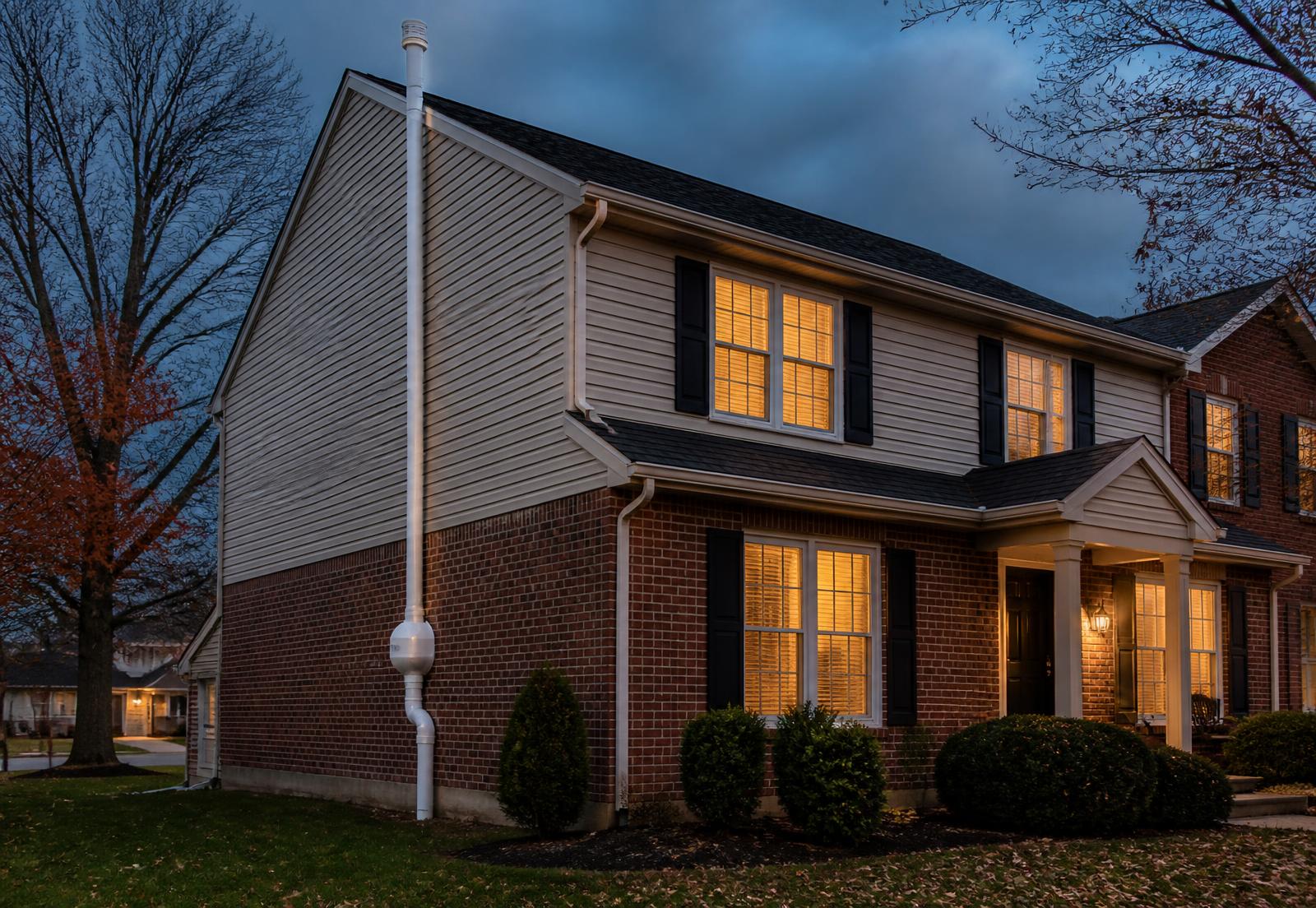
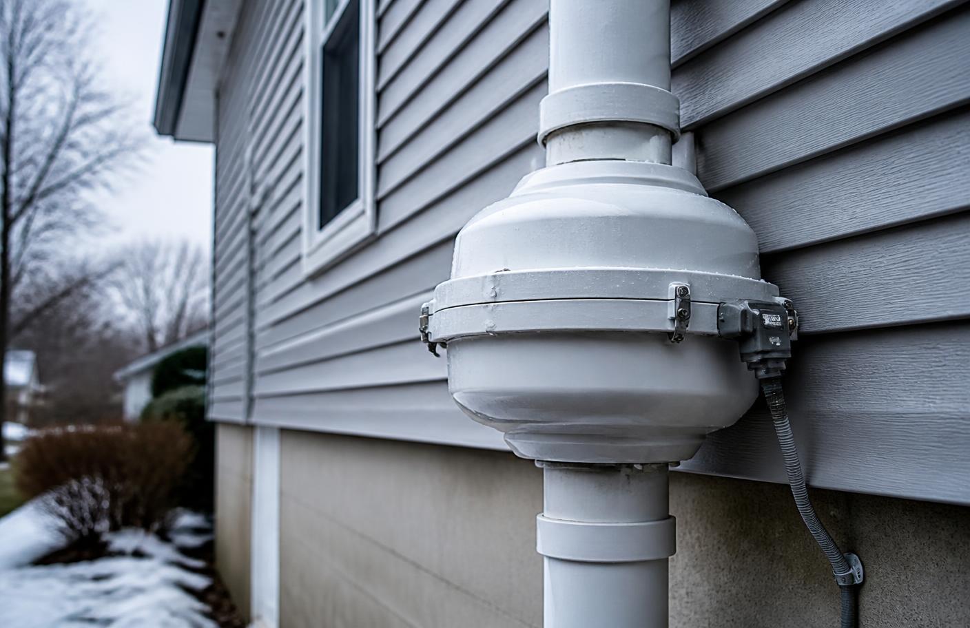
We look for existing chases, closets, and exterior wall paths that let the pipe travel from the suction pit to the attic or roofline with the fewest bends possible, since each 90-degree elbow adds resistance the fan has to overcome. Where an interior route would require cutting into finished ceilings or walls, we route the system up an exterior wall instead and paint the PVC to match the siding.
Suction Pit Excavation and Sealing
We core a 4 to 6 inch hole through the concrete slab at the chosen suction point, then hand-excavate a small pit beneath it, typically 5 gallons or so of soil and aggregate, to create an open cavity the suction pipe can draw from efficiently. The pipe is set into this pit and the surrounding slab opening is sealed with a pipe boot and polyurethane sealant so the suction is pulling from beneath the slab rather than leaking room air back down the same hole.
For crawl space installations, this step is replaced by sealing a reinforced polyethylene membrane across the entire exposed soil area, taped and sealed at all seams, piers and the foundation perimeter, with the suction point set beneath the membrane itself.
Sump Pit Integration
When a home has an open sump pit connected to perimeter drain tile, we fit it with a sealed, gasketed lid that includes a port for the suction pipe, effectively turning the entire drain tile loop into part of the suction field. This is often more efficient than a standalone suction pit because drain tile already provides a path for suction to spread around the foundation perimeter.
Electrical Work and Fan Mounting
Radon fans need a dedicated, properly grounded circuit, and we run electrical work to meet standard residential wiring practices, including GFCI protection where the fan is installed in a garage or exterior location per code requirements in those settings. The fan itself is typically mounted in the attic or on an exterior wall, ideally not directly above any living space, and oriented per manufacturer specification so condensation drains back toward the pipe rather than pooling in the fan housing.
We size the fan to the static pressure the system needs based on suction testing during the estimate, rather than installing the same fan model on every job regardless of foundation size or soil permeability.
- Dedicated electrical circuit sized and installed to code
- Fan orientation and mounting per manufacturer specification
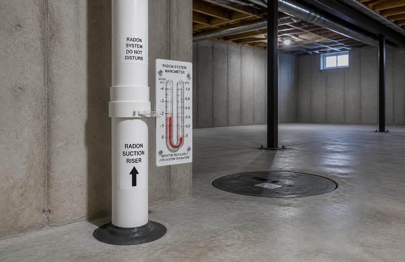
- U-tube manometer or digital gauge installed on visible pipe run
- Labeling at the electrical panel identifying the radon system circuit
Exhaust Termination and Backdrafting Checks
The exhaust point always terminates above the eave line of the roof and away from windows, doors, and any fresh air intakes, consistent with standard radon mitigation system design guidance, to prevent exhausted soil gas from re-entering the home or an adjacent structure. We check the discharge point relative to nearby windows on multi-story additions and next-door structures on tightly spaced urban lots common in older Indianapolis neighborhoods.
Before finishing, we test for backdrafting on combustion appliances near the suction pit, such as a natural draft water heater or furnace, to confirm the mitigation system is not depressurizing the mechanical room enough to interfere with proper venting of those appliances.
Final Walkthrough and Homeowner Handoff
Before we leave the job site we walk the homeowner through the finished system: where the gauge is, what a normal reading looks like, how to recognize a fan failure, and when to schedule the post-installation retest. We also leave a label at the electrical panel and near the fan itself identifying the system so future contractors or inspectors do not mistake it for an ordinary vent pipe.